
|
|
SUBSIM: The Web's #1 resource for all submarine & naval simulations since 1997
|
SUBSIM: The Web's #1 resource for all submarine & naval simulations since 1997 |
 12-01-07, 09:38 PM
|
#31 |
|
Sea Lord
 Join Date: May 2005
Location: Under a thermal layer in chilly Olde England
Posts: 1,842
Downloads: 0
Uploads: 0
|
Stop press! Al actually manages to tidy his desk without assistance from his wife :rotfl:
Now I can actually see what I am doing! and yes, that actually is tidy compared to how it was before. 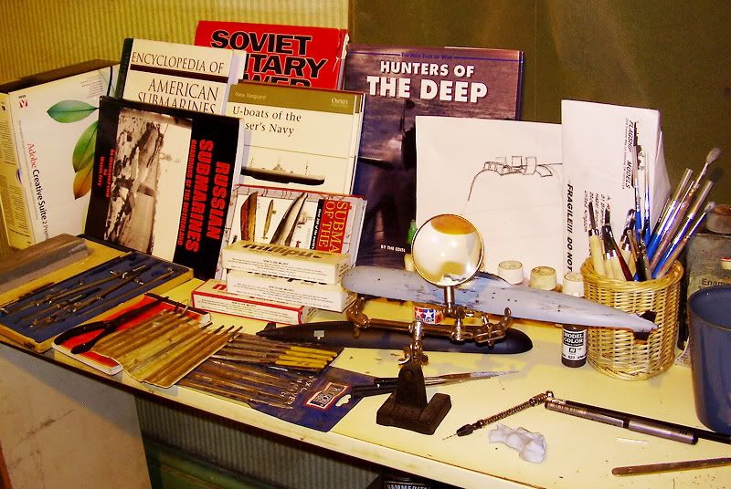  Chock Chock
__________________

Last edited by Chock; 12-01-07 at 10:01 PM. |

|

|
|
12-02-07, 01:03 AM
|
#32 |
|
Sea Lord
Join Date: May 2005
Location: Under a thermal layer in chilly Olde England
Posts: 1,842
Downloads: 0
Uploads: 0
|
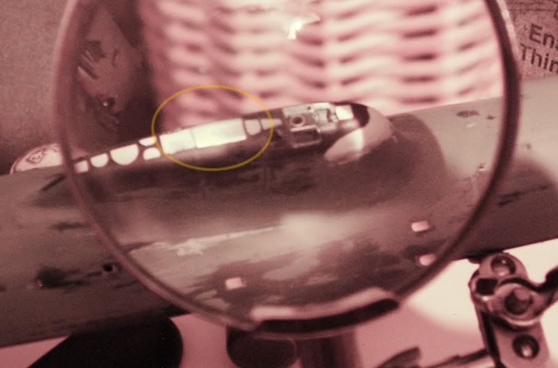
A shot through the magnifier, the highlighted circle shows the position of more fun with alloy litho plate, this time, inserted into the sail to allow more accurate scribing of the hatches on top of the escape module:
 Chock Chock
__________________
|
|
|
|
|
12-03-07, 07:26 PM
|
#33 |
|
Sea Lord
Join Date: May 2005
Location: Under a thermal layer in chilly Olde England
Posts: 1,842
Downloads: 0
Uploads: 0
|
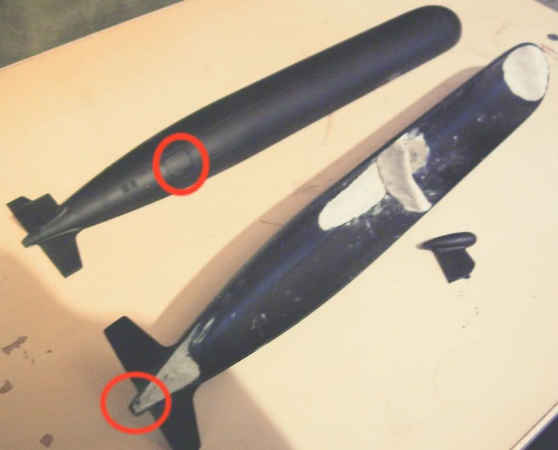 Pic of what's going on next. The vertical fin is added to the lower half of the hull (this is a good fit and only minimal filling will be needed). The doors for the creeper motors (circled) are fixed in the closed position, the creeper motor doors are not a fantastic fit, so a bit of sanding and filling will be needed, but I want the door shut lines to be visible, so not too much will be required despite the less than great fit. The stern where the screw is to be added is incorrect in profile (circled), the real 971 has a much longer 'tail' extension, presumably to better clear the towed array, so that needs to be extended and reprofiled. Also visible in this pic is the towed array pod and vertical fin, this being the larger one of the type fitted to Akulas prior to the Gepard, since the sail has been restyled to suit the earlier type of Akula. The pod itself also needs a tweek to be correct and show where the antenna wire exits the pod, and some detailing needs adding to the top of the pod, but this is a minimal fix and will be easy to do. The sail is in fact incorrect for both variants as the kit comes, but is more like the slimmer Gepard type, which was why the sail needed so much work! I think the larger array housing is more visually pleasing however (the smaller Gepard type is also in the kit as an option), so all that faffing around to get the sail to look like an earlier variant was worth it in my opinion, even though making the Gepard would have been easier! Also visible in this shot is the interior bracing, with putty, which I added to prevent the top half of the hull flexing and cracking the filler used on correcting the way the sail fairs into the deck, with additions at the bow and stern to facilitate reprofiling these areas too. The bow is actually slightly incorrect in shape, although this will in fact be masked by the way I am choosing to display the model, so I can actually ignore that part if I like, but the stern ccertainly is going to get tweeked. With the sail largely sorted and the hull coming together, things should move along a bit quicker now! Chock
__________________
|
|
|
|
|
12-03-07, 07:31 PM
|
#34 |
|
Sparky
 Join Date: Feb 2007
Location: LA Ca.
Posts: 152
Downloads: 0
Uploads: 0
|
Chock. After this you are more than ready for a nice scale RC conversion build. Anyone that puts this kind of work in a static model is more than Worthy of it. Good job!
U812 |
|
|
|
|
12-03-07, 08:11 PM
|
#35 |
|
Sea Lord
Join Date: May 2005
Location: Under a thermal layer in chilly Olde England
Posts: 1,842
Downloads: 0
Uploads: 0
|
Yeah, I'll probably get around to doing an RC one at some point. I've made some scale RC aeroplanes in the past - last one I did was a quarter scale Fokker DVII with a four stroke engine - I'm still having nightmares about how long it took to hand paint the lozenge pattern fabric I covered that thing with. And I damn near turned myself into a eunuch once starting it up! But it did look very cool and the bigger ones always fly better.
I guess that's true with subs, I imagine the bigger RC subs look better as far as scale against the waves go, so if I ever did an RC one, I think it would have to be a big mother and not some tiny one, although I bet they are fun too, I have a small RC tiger tank actually, and thats certainly good fun. Chock
__________________
|
|
|
|
|
12-04-07, 04:09 PM
|
#36 |
|
Sea Lord
Join Date: May 2005
Location: Under a thermal layer in chilly Olde England
Posts: 1,842
Downloads: 0
Uploads: 0
|
Stern propshaft housing extension added and waiting to be sanded and neatened up, and yes, the hull halves have been joined up too, at last:
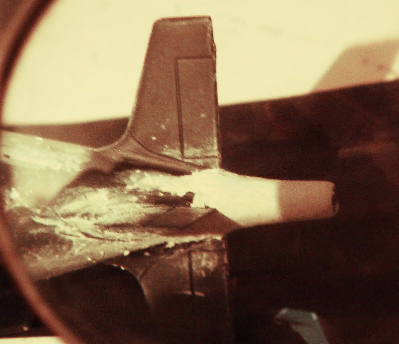 I flattened the kit's original stern and butt-joined an extension made from a scrap section of the sprue from the kit, and then sculpted filler over it, it might take a few goes with filler to get this to blend correctly, but it's reasonably close already with this first covering, so that's a bonus. This is based on the best guess from several (conflicting) blueprint drawings kicking about on the 'net and some photographs probably taken by a dockyard worker with a camera up his jumper, needless to say, there aren't exactly tons of pictures of top secret Soviet/Russian submarine scews, although once again, Wayne Frey's book comes up trumps with one or two. Also visible on this shot (just) is the join where the bottom fin is added, although the fin is edge-on in this picture, this needs sorting out too. The trailing edge of the fins will need thinning out a bit to come to a sharper edge. Chock
__________________
|
|
|
|
|
12-04-07, 05:58 PM
|
#37 |
|
Sea Lord
Join Date: May 2005
Location: Under a thermal layer in chilly Olde England
Posts: 1,842
Downloads: 0
Uploads: 0
|
Ass end cleaned up a bit and fin with pod added:
 Chock Chock
__________________
|
|
|
|
|
12-05-07, 07:35 AM
|
#38 |
|
Sonar Guy
 Join Date: Jan 2006
Location: The cold part of a Helicopter, the back.
Posts: 395
Downloads: 0
Uploads: 0
|
Looking forward to seeing this finished with comparison to what it used to look like in the first pictures.
Alot of time and effort gone into it! Wish I had the same amount of time and dedication to something like that.
__________________

|
|
|
|
|
12-05-07, 02:46 PM
|
#39 |
|
Sea Lord
Join Date: May 2005
Location: Under a thermal layer in chilly Olde England
Posts: 1,842
Downloads: 0
Uploads: 0
|
More tweeking of the ass end, here you can see how overscale the thickness of the fin trailing edges is:
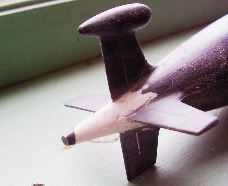  Chock Chock
__________________
|
|
|
|
|
12-05-07, 06:02 PM
|
#40 |
|
Sea Lord
Join Date: May 2005
Location: Under a thermal layer in chilly Olde England
Posts: 1,842
Downloads: 0
Uploads: 0
|
Bit of a naff picture, but you can see that the filler has been sanded to the correct shape and blended into the original rear of the hull, I gave this bit a quick coat of grey primer to highlight any blemishes or bits that neded sorting. You might also notice that my nice filler job on the pod will have to be redone because dumbass Al accidentally knocked it off while sanding the filler and had to re-attach it - Doh!, so that bit will need to be smoothed and filled again, although it was kind of a blessing in disguise, as it was a lot easier to sand with the fin off (once I had stopped swearing in a Homer Simpson stylee).
 Chock Chock
__________________
|
|
|
|
|
12-05-07, 07:58 PM
|
#41 |
|
Sea Lord
Join Date: May 2005
Location: Under a thermal layer in chilly Olde England
Posts: 1,842
Downloads: 0
Uploads: 0
|
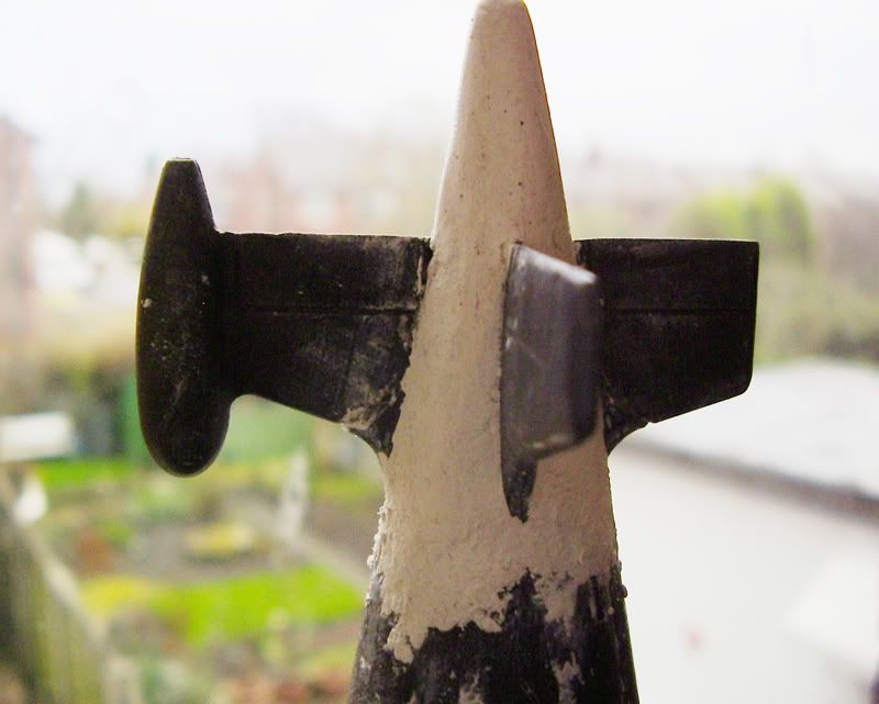
Shot through the desktop magnifier and with the colour tweeked a bit in Photoshop so you can see the detail as my camera takes crappy shots in anything but daylight, here is the stern now it has been sorted out and had the gaps in the joins for the fins filled in:
 Chock Chock
__________________
|
|
|
|
|
12-07-07, 10:13 AM
|
#42 |
|
Sea Lord
Join Date: May 2005
Location: Under a thermal layer in chilly Olde England
Posts: 1,842
Downloads: 0
Uploads: 0
|
Wasn't totally happy with the towed array pod, and so I tried to refine the shape, but the plastic is not good enough to hold the level of detail I wanted, so I inserted a 1.5 millimeter alloy tube into the end and faired filler into it, this will need sanding again to be nice and smooth but you can see it at the 'pre-sanding' stage here:
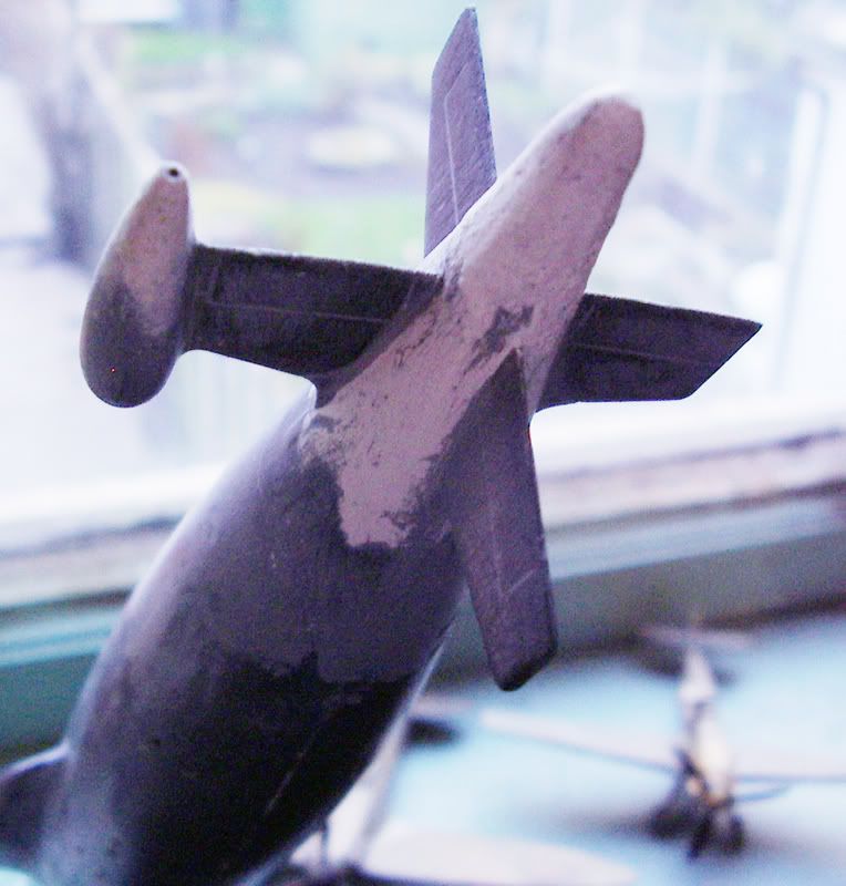 you can also see that the thinning of the fins trailing edges has been started, they need squaring off, but they are now very much more like the correct scale thickness of the ones compared to the real thing. Still on topic, I'd just like to say a quick thank you to Wayne Frey, author of the book 'Russian Submarines, Guardians of the Motherland' - following me asking some questions about some detailing on the 'akula' in the subpirates forum, Wayne very kindly contacted me and offered to answer a few questions I had, and he has been very helpful indeed. A real nice guy, look out for his subcommittee review of the 2008 submarine Almanac by the way. Chock
__________________
|
|
|
|
|
12-08-07, 11:41 AM
|
#43 |
|
Sea Lord
Join Date: May 2005
Location: Under a thermal layer in chilly Olde England
Posts: 1,842
Downloads: 0
Uploads: 0
|
Time for an update, here is an overall picture of the revised and tweeked hull at the moment:
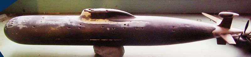 That's a fair few changes to get it to a more correct shape! Here's the smoothed out towed array pod now with an alloy insert to make the array wire exit hole the correct size and allow it to be filed to a more corect profile without running out of plastic, that's a 1/72nd scale Spitfire you can see in the shot, which gives you a good idea of the size of the akula model: 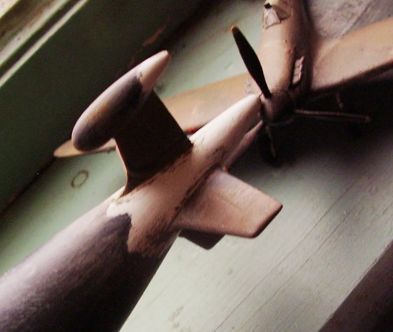 And if you don't know how big a 1/72nd scale Spitfire is, here's the same model with a 2 pence piece to compare it against: 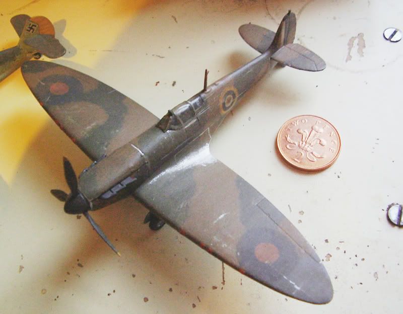 The hull halves are not the best fit in the world, not disastrously bad, but quite a bit of sanding and filling is required to get rid of the join line, you can see some of the more extreme filling on the middle here: 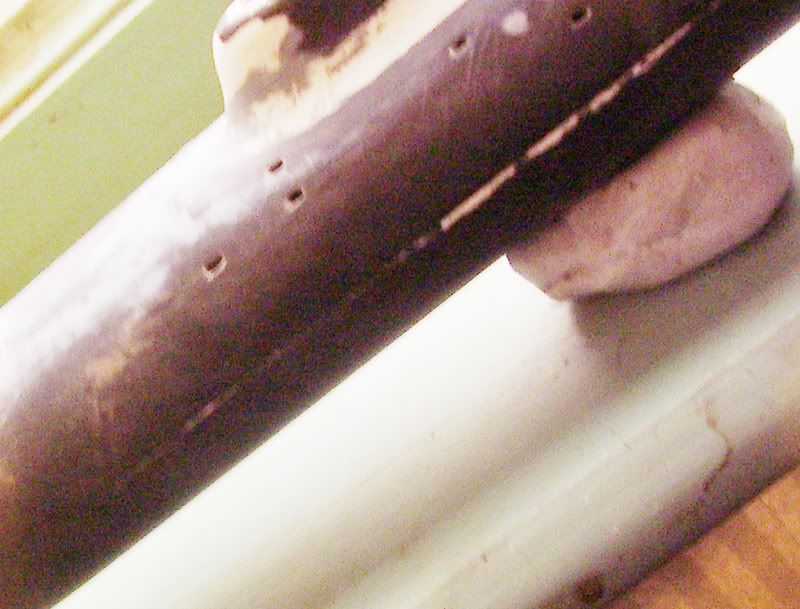 And so, detailing of the hull comences, since I removed the raised detail from all but a few places, there's quite a bit of this to do, here you can see I have begun to scribe in the communications pod doors, the fairleads and centreline door break have yet to be added:  Chock Chock
__________________
|
|
|
|
|
12-08-07, 11:09 PM
|
#44 |
|
Sea Lord
Join Date: May 2005
Location: Under a thermal layer in chilly Olde England
Posts: 1,842
Downloads: 0
Uploads: 0
|
This was fun, the seawater intakes in the kit are the wrong shape and they are not very accurate size-wise either. This is where Wayne Frey's knowledge came in handy, he kindly answered a few of my dumb questions about them and from that and inspection of some pics and diagrams, I made new ones. They were cut from thin polycarbonate and laminated three deep and then clamped together so they could be filed to the correct profile all in one go:
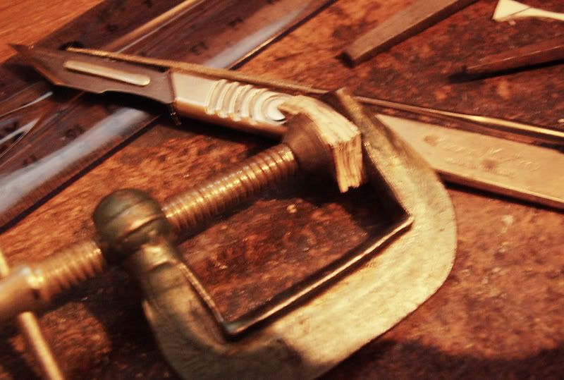 This is where the world wide interweb comes in handy, along with Photoshop. In this (tweaked for clarity) shot you can see me holding the six clamped and laminated pieces in front of a fairly accurate schematic drawing which I found on the 'net, although it was drawn at 1/400 scale and of course does not display at that size owing to a different monitor resolution, it was a relatively simple matter to resize the image to the correct scale and 'Bob's yer uncle', a decent placement guide for the new intakes, which, coupled with the pics of the Gepard backing out of the construction hall in Wayne's book made life a lot easier. 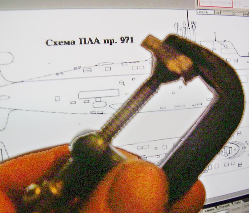 Fixed in place and awaiting some tidying, here's a quick shot of one of them through the magnifier:  Chock Chock
__________________
|
|
|
|
|
12-09-07, 07:43 PM
|
#45 |
|
Sea Lord
Join Date: May 2005
Location: Under a thermal layer in chilly Olde England
Posts: 1,842
Downloads: 0
Uploads: 0
|
Episode IV: Stop Using Sex as a Weapon.
The other day my wife walked past me as I was working on this sub model and said 'How's your phallic symbol coming along?' Now, you have to admit she has a point, quite apart from the shape of nuclear subs, there's the fact that they are indeed long, hard and full of seamen. So it was quite funny when I pointed out something to her tonight whilst again working on the sub model. I opened Wayne Frey's book on page 40, which shows two pictures of the rear deck communication buoy housing doors and fairleads. 'Is it me, or do those look like a woman's sexual organs?' I asked her (in slightly more crude language I admit). 'Well, I thought you were more of a breast man myself' replies my wife, 'But no, it's not you, it does indeed look like that' Anyway, in reshaping the model a lot and losing the raised detail, the molded detail for this bit was lost, which was not a big deal as it wasn't too accurate anyway, so here it is in the process of being remodeled: 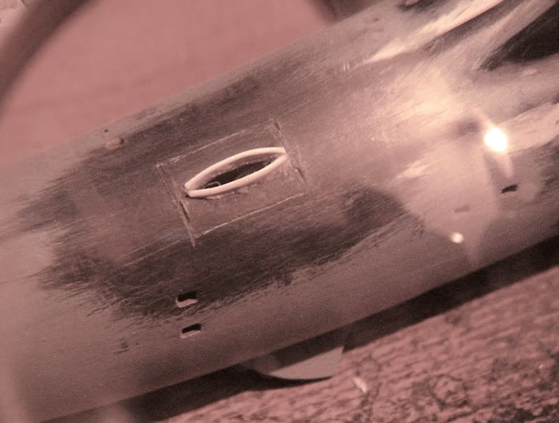 I know what you're thinking, that looks like a... Chock
__________________
|
|
|
|
 |
|
|


 Linear Mode

